CR Side Mount Post Kit Installation Guide
Models covered: P36B-SM(D) | P42B-SM(D) | P-SM-36L(D) | P-SM-42L(D)
8 steps 4 ft max post spacing 5 year warrantyBefore You Begin: Improper installation can lead to failure of the rail system, which can cause serious injury or death. You and your installer make the final determination of the means and methods appropriate for your site. If you are unsure or uncomfortable with any step, hire a licensed and bonded contractor.
Start here
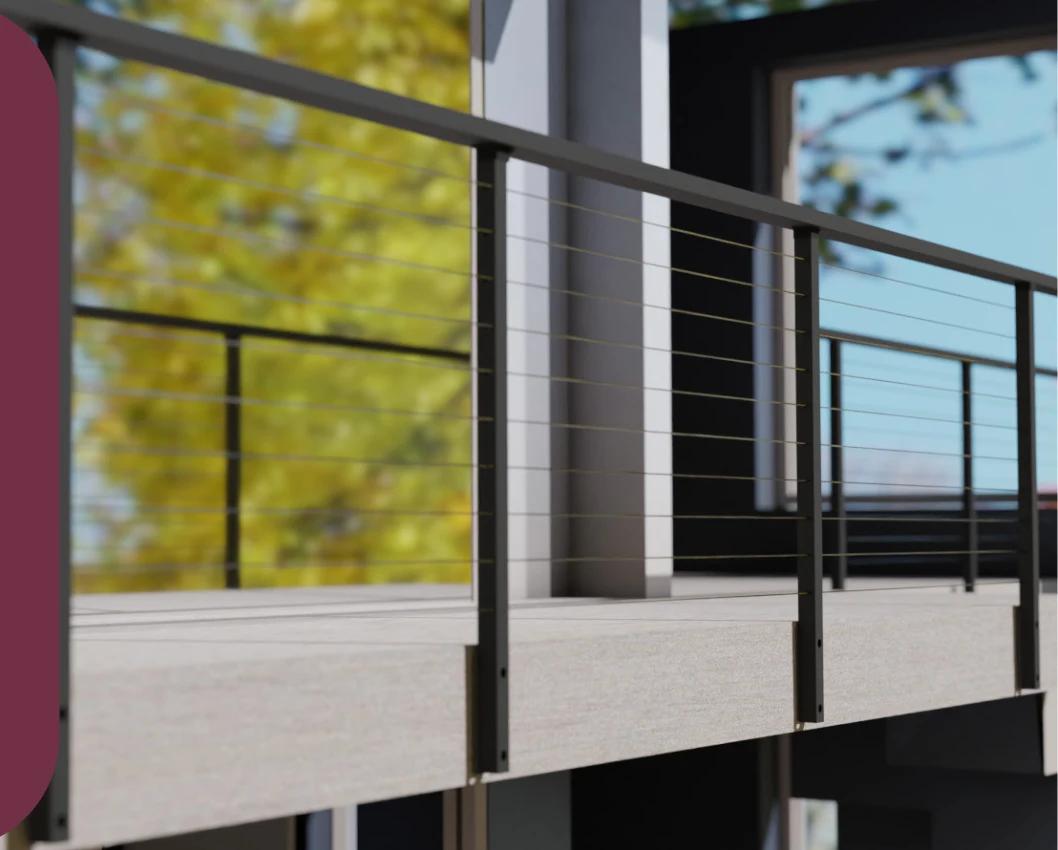
How to install a CR side mount post kit on the side of a deck or floor — this one guide covers BOTH the side mount PLAIN post and the side mount CABLE post, because the post kit and its mounting procedure are the same hardware.
Watch the installation video
Play the CR installation video on YouTube
- Safety precautions
- Means and methods disclaimer
- Time and tools
- Part 1: Mounting your post to a wood or concrete surface
- Part 2: Installing top rail brackets and cable sleeve protectors
- Connecting rails
- Need help
Safety precautions
Read every message in this section before you touch any component. They apply to every model this guide covers and to every installation surface.
WARNING The hardware we ship may not be the hardware your site needs
Please make sure the hardware and tools we provided will be right for your install (read the means & methods disclaimer). IT IS POSSIBLE YOU NEED DIFFERENT HARDWARE & METHODS.
Please take your time to do your installation. If you are unsure or uncomfortable with the installation, we highly recommend hiring a licensed and bonded contractor.
WARNING Anchor strength depends on the hole and the concrete
The strength of the anchor is dependent on the hole size & concrete integrity. A hole that’s too big, or concrete that’s not up to standard grade, can make the anchor wiggle or possibly come out. This is what can cause a rail to fail & fall over.
WARNING Post spacing and the 4-inch sphere test
The recommended distance between posts is 3 to 4 feet, with 4 feet as the maximum. Our cable posts have holes drilled 3 1/8" centre-to-centre. For compliance with the 4-inch sphere test standard, maintain this spacing AND apply 200 lbs of tension on each cable. Tension gauges are available online and at local retailers.
CAUTION Aftermarket sleeve protectors need checking first
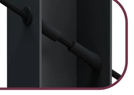
Our cable sleeve protectors fit standard 1/8-inch cables. Aftermarket stainless steel protectors may need larger holes drilled — check size compatibility with our post design before you drill. End slip-in terminals are an option. If you have already drilled larger holes by accident, contact customer service for a full refund.
Means and methods disclaimer
In no event shall CR Fence & Rail Inc have any responsibility, control over, charge of, responsibility, or liability for the means, methods, techniques, sequences, or procedures, or for safety precautions in connection with the installation of the railing, since these are solely CM/GC’s, Subcontractor’s, and Owner’s responsibilities.
Each installation site differs widely ranging from the construction & condition of attachment points, local building & safety code, local construction code, and local means & methods.
CR Fence & Rail Inc’s installation guide (whether it be in text, illustration, video or in support discussion) constitute for ideal installation condition. There is no ideal installation in real life. There is no substitution for consulting a local licensed contractor, architect, engineer, nor code inspector.
CR Fence & Rail Inc’s installation hardware and tools are provided as building material and does NOT constitute as the specific nor final installation hardware. Once again, you and your installer must make the final on-site determination to the specific means and methods of installation appropriate for your installation.
Following CR Fence & Rail Inc’s instruction does NOT constitute as proper installation as you and your installer must make the final means & method determination. Improper installation can lead to failure of rail system which can cause serious injury or death.
If your printed booklet names a different company in this clause, this page is the current one: CR Fence & Rail Inc is the registered entity. Earlier printings carry an out-of-date name.
Time and tools required
Time required
- Allow an hour for the first post and less for each one after it
Tools required
- An electric drill or hammer drill
- Wood pilot-hole bit (smaller) or masonry drill bit (larger), both included
- Nut socket and bit extension — included
- The depth-measuring pencil included in the kit
What is in your kit
1Wood pilot hole drill bit
1Masonry drill bit
1Drill bit extender — for the hex bit and the nut holder
1Depth measuring pencil
1Ruler
1Hex bit
1Hex nut / bolt driver
1Bubble leveler
4Lag screws — for wood
4Wedge anchors — for concrete
4Flat washers
2Side mount baseplates
2Bottom end caps
4Hole covers
4Flat-end screws
2Side mount plain posts — with 2 post caps, 2 brackets, 6 self-drilling screws
2Side mount cable posts — with 2 top plates, 4 flat-end screws, 8 self-drilling screws, 40/48 cable sleeve protectors
2Side mount stairs cable posts — with 2 brackets, 8 self-drilling screws, 40 cable sleeve protectors
Masonry tools and hardware (for concrete)
5/16" (8mm)Anchor Bolt
5/16" (8mm)Masonry Drill Bit — *SDS+ available upon request
—Diamond Core Drill Bit — for hard stone, *available upon request
This will be a tight fit. In fact, the specification calls for the drill bit and anchors to be the same size. Some installers use a 3/8" drill bit to make the installation easier, and other installers wiggle the drill bit to bore the top of the hole slightly bigger. We are aware of the tight fit and we only recommend using our masonry drill bit without wiggling.
Part 1: Mounting your post to a wood or concrete surface
1Set the post distance
Mark the location for the first post. Measure a maximum of 4 feet to the second post, continuing for additional posts. Ensure the markings are from the CENTRE of one post to the CENTRE of the next.
 2
2 Mark and pre-drill the holes
Position the metal plate on the side flooring and mark the hole locations with the provided pencil.
FOR WOOD — use the wood pilot-hole bit (the smaller bit). FOR CONCRETE — use the masonry drill bit (the larger bit). Using an electric drill, drill pilot holes following the marked points.
 3
3 Depth check (concrete only)
Use the pencil’s flat end to check the depth of the holes, ensuring they are deep enough for the anchors. Hole NOT deep enough: keep drilling deeper. Hole TOO DEEP: be careful not to insert the anchor too deep.
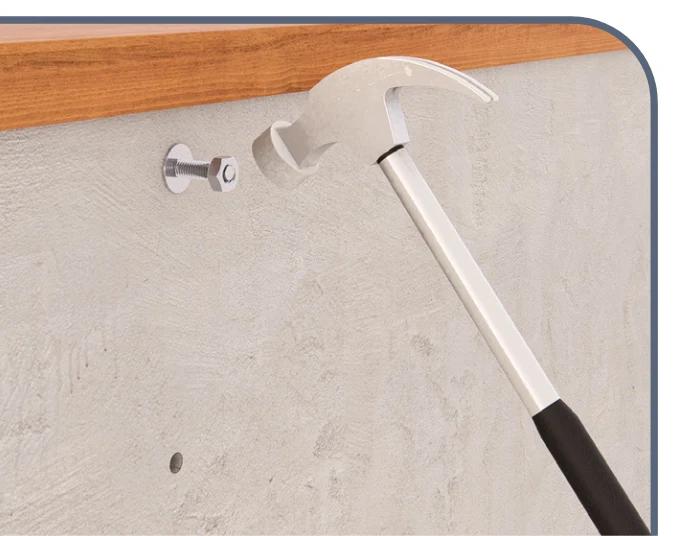
4 Install the anchors (concrete only)
Once the holes are made and the depth is verified, hammer the anchors into the holes. Then place the post on the anchor and ensure the nut has enough thread for secure tightening.
To avoid pushing the anchor too deep, stack two washers and two nuts at the end of each anchor before hammering.
 5
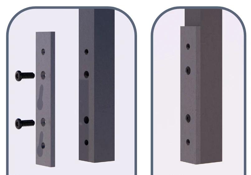
5 Attach the metal plate
Line up the metal plate with the pre-drilled holes in the post. Secure it using flat-end screws in the second and third holes.
If your side flooring does not have an edge lip, you can skip this step.
 6
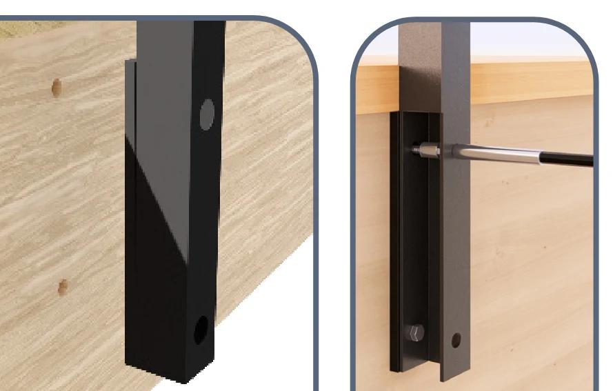
6 Secure the post to the side of the flooring
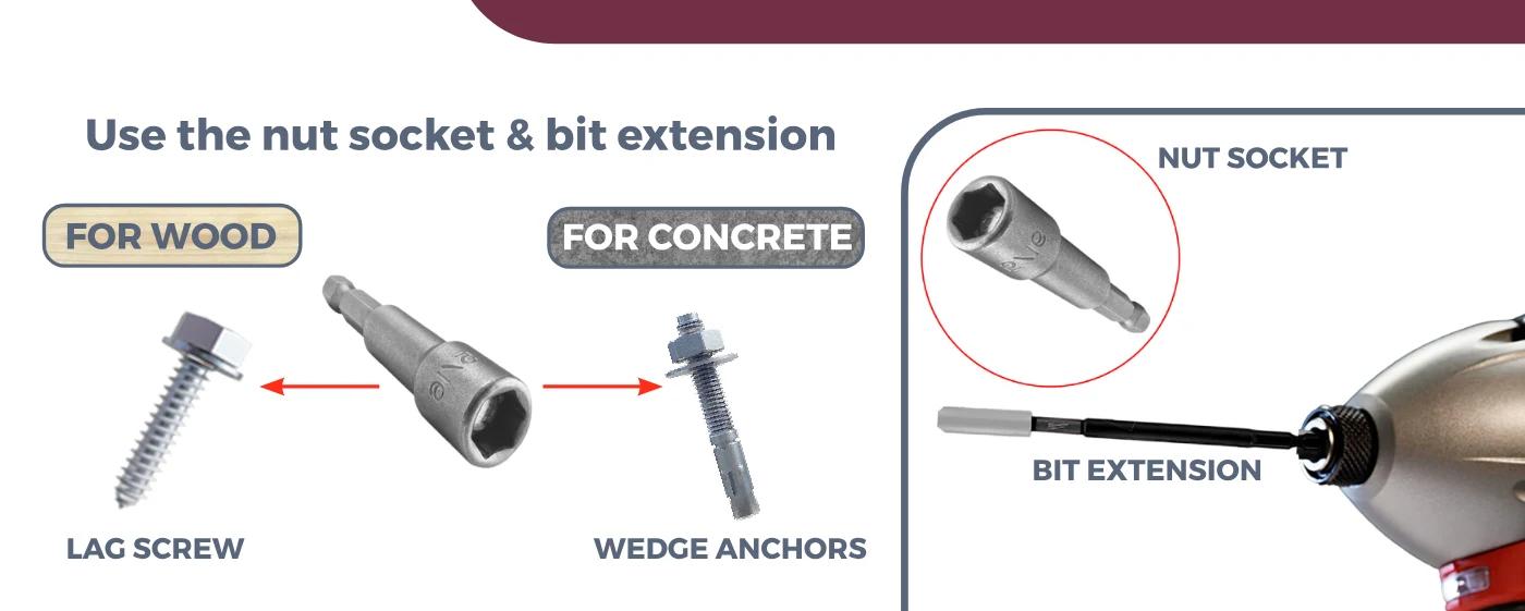
Use the nut socket and bit extension.
FOR WOOD — align the post with the drilled holes in the side floor, then insert and screw the lag screws through the post and into the side floor using an electric drill with the bit extender and nut socket.
FOR CONCRETE — remove the nut and washer from the anchor bolt, position the post so the base plate holes align with the anchor bolts, then attach the nut and washer for each bolt and tighten with an electric drill using the bit extender and nut socket.
Make sure the anchors and screws go through the metal plate AND into the side flooring securely.
 7
7 Hole cover, top and bottom cap
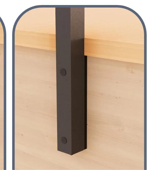
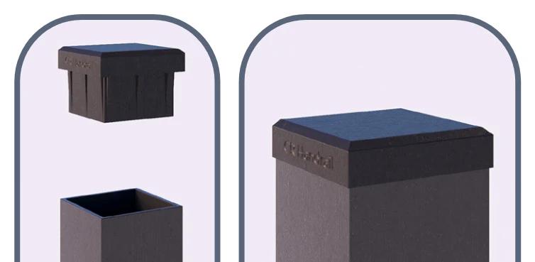
Plug the holes with the provided hole cover — it should snap in place, no adhesives needed. If you are not installing a top rail, attach the post cap to seal the top of the post, then place the bottom end cap at the bottom of the post.
Part 2: Installing top rail brackets and cable sleeve protectors
The top rail is sold separately.
8.1Top rail bracket — for a plain post
Install the top rail bracket onto the post with the top of the bracket flush with the top of the post. Make sure the hole is facing inwards, or towards the second post. Secure the bracket to the post using 1 self-drill screw per bracket.
This post can be used with a top rail and middle rail, or with a baluster guard rail and top rail.
8.2Top rail bracket — for a stairs cable post
Attach the top rail bracket to the post and secure it using 2 self-drill screws per bracket. When attaching the bracket, ensure the flat top post does not stick out, to allow proper placement of the top rail.
Connecting rails: top rail connectors
Top rail connectors join one CR rail kit to the next, turn a corner, or close a run against a wall. They are fittings used inside the installation above, not a separate job.
- TRC-SFm / TRC-CFm — straight fixed metal connector, for an in-line join.
- TRC-SAp — straight adjustable connector, where the two rails are not quite in line.
- TRC-CAp / TRC-BAp — corner and 180° adjustable connectors.
- TRC-Wallv1 — L bracket, for terminating a rail into a wall.
- TRC-EndM — metal top rail end cap, to close an open rail end.
Fit the connector before you secure the joint: seat both rails fully into the connector, then drive the self-drilling screws through the pre-made holes. Use 2 screws on each end of a top rail connector, on the bottom side.
Watch the top rail connector video
5-year warranty
Register your product within 30 days to activate the warranty.
To view our full warranty policy, visit www.fencerail.com/warranty.
Need help?
We are here to help you get it right. Text us a photo of the problem — it is the fastest way for us to see what you are looking at.
Call or text with photos: (800) 420-0432
WhatsApp: (775) 324-8877
Missing parts? We will replace them free — www.fencerail.com/parts
We can help with
- Connecting multiple railings
- Technical drawings
- Complicated installations
- Installation error
- Missing parts
Source of this guide: Transposed from the shipped Post Kit (Side Mount) Installation Guide (48 pages), read from its own text layer. The legacy instruction-guides page served this same file under two headings — "Side Mount Plain Posts" and "Side Mount Cable Rail Post" — which is CORRECT: it is one post kit. This page says so, which the legacy page never did.